


Geographic Coordinate System
The Geographic Coordinate System (GCS) dialog is used to report, select or delete a GCS for the current model in the design file.
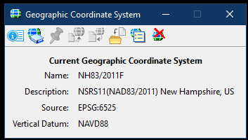
Find this dialog from the Drawing workflow, Utilities tab. Clicking the Coordinate System button will open the Geographic Coordinate System dialog shown below.
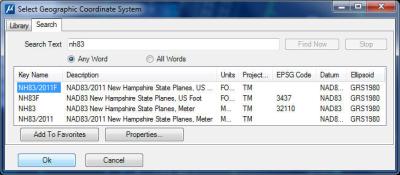
The GCS can be manually set for the current design file. From the Geographic Coordinate System dialog, select the From Library button (the second button from the left) to get the Select Geographic Coordinate System panel (shown to the right).
At this point there are two choices, the Library option and the Search option. Each option is presented as a tab. Of the two choices, the Search option is easier. From the Search tab, enter the partial GCS Name of NH83 in Search Text. This will present all of the matching New Hampshire State Plane options of GCS.
Select the target GCS for this project from the Search Results and then click the Add To Favorites button. This GCS may be used now and will be available in the future. Return to the Library tab and select the target GCS which was just added and is now available in the Favorites folder. Select OK to set.
The following warning panel might appear.
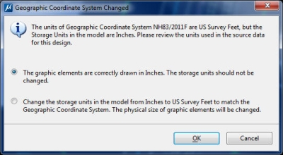
Accept the default selection indicating that the elements are drawn correctly.
In order to set/check the Vertical Datum, select the Details... tool (first button) of the Geographic Coordinate System dialog box. The Geographic Coordinate System Properties panel of the currently set GCS will appear. At the bottom is a section for Coordinate System Modifiers. Confirm that the Vertical Datum is correct or change if necessary. Click OK when finished.
Save Settings to save the Coordinate System for this model. If the drawing contains multiple models, this step will need to be repeated for each one.