


Tips for Creating Color Plans
This document is not intended to cover the entire process of creating colored presentation plans. Many of the tasks can be done by multiple methods. There is typically no correct or preferred method to creating the color fill patterns. With experience, each individual will find the method that works best for them. The tips below provide a general outline to the process. Suggestions for enhancing this document are welcome and encouraged.
The first step is to create the new drawing to contain the color fill areas. Hearing plans will be called #####her.dgn and other color drawings should be #####clr.dgn. The # characters represent the project number.
Attach other project drawings as reference files.
Level and color settings are set by selecting the appropriate Task from the NH_HER Tasks list.
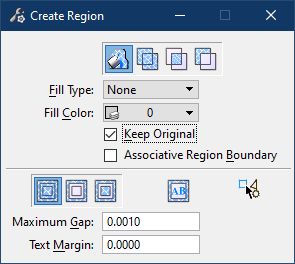
Create filled areas by using the Create Region tool.
Use the Flood method of the Create Region tool and select a point inside the area to be filled. Checking the Keep Original box will prevent graphics defining the boundary of the fill from being deleted. On 3D drawings, better results will be obtained if the referenced drawings are flattened.
Features such as buildings, waterways, and woods lines can be outlined if desired. This can be done by copying the feature outlines from their original drawing onto the HER or CLR drawing. Set the correct color and weight by selecting the item from the task menu. Use the Change Element Attributes tool to alter the lines.
A pen table, hearing plan.tbl, has been developed that will adjust colors and line weights of elements on the drawing when plotted. To use the pen table, first select the printer where the plot will be sent. Then select Attach from the Pen Table menu on the Print dialog box. Pen tables are stored under the workspace folder in ...\standards\tables\pen\. When modifying plot color, weight, etc., the pen table refers to the reference drawings by logical name. When manually attaching reference files, be sure to define the logical names appropriately.
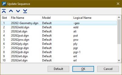
Before plotting the color plan, the update sequence of the references should be modified. Reference manager Settings>Update Sequence. Any Aerial files should be top in the list and the Active Design file should be second (top if no aerial files). This will let all other detail drawings be drawn after the colors so they will show up on top. Element priority is set to -100 for existing color floods so that proposed floods will be on top. This can be done as part of the pen table also.