


Working with Shape Files
Shape files are used to import GIS data into CAD/D products.
Shape files actually consist of 4 files, .shx, .dbf, .prj, and the .shp.
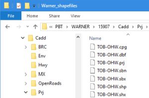
All four files should be present for a successful attachment. Save any shape files to the originating Bureau's/Section's directory. Shape files created by Bureau of Environment have units in US Survey Feet.
Shape files are attached to a DGN file as a reference file.
- Open MicroStation or OpenRoads Designer in the correct project and select the appropriate .dgn for the import.
- Open the Reference Files Dialog box and shut off the display of all reference file except the ali.dgn.
- Use Tools>Attach> and browse to the directory you saved the files and select the .shp file.
- Set the attachment method to Coincident World and hit Open.
What if the Attachment is in the Wrong Location!
Depending on which coordinate and unit settings were in place when the shape file was created, it may appear far away from the project detail when attached. Here are some things to try to resolve the problem.
- Select the shape file in the Reference File Manager and toggle the True Scale button.
- If that doesn't work, try changing the Scale of the master : reference ratio to 1.000000 : 3.28083.
- If it is still not in the proper location, detach the reference attachment and attach it again with the Orientation set to Geographic - AEC Transform.
- When all else fails, contact the CAD/D support group for assistance.
Creating the MicroStation Elements
First ensure that the shape file came into the correct location. You can display aerial photos or additional detail to confirm the shape's locations. Compare the display to any pictures or plans provided by the source.
In the reference files dialog box select the attached shape files again and use File > Merge into Master, and click in the view to copy their contents into the drawing. This will also detach the reference files.
Turn off all other reference files so that only the shapes are displayed. The shapes and points will be in levels of the same name as the shape files they came from.
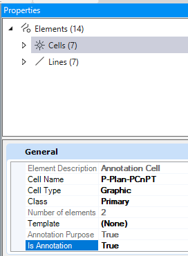
Note that point elements in shape files are nearly invisible in MicroStation. Cells can be placed at the points so they can be seen more clearly. Choose the Element Template associated with the feature the shapes represent. (i.e. Invasive Species). This sets all element attributes appropriately.
A vba macro can be run to place circle cells over any points. Use the Key-in vba run Zero2Cell circle 5
If the scale is not specified, the annotation scale is used.
If the cells are not readily visible, select the cells and check that their Is Annotation property is set to True.
Use Element Selector to select the shape by level, and element type (line point or linestring).
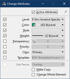
Select the appropriate Element Template for the type of feature the shapes represent to set the correct level, linestyle, color, etc. . (i.e. Invasive Species).
Next, select the Change Element Attributes tool and change the shape elements Level, Color, Style and Weight to the active attributes.
If not already done, detach the .shp reference file and delete the unneeded level from the drawing. When the shapes were copied in, MicroStation placed them in a level named the same as the shape file (i.e. KW).
Review your work and save it.